BuggyNews Buggy Forum
https://buggynews.com:443/

Suzuki 1000cc Geo Metro / Swift Powered road legal buggy
https://buggynews.com:443/suzuki-1000cc-geo-metro-swift-powered-road-legal-buggy-t29580.html
Page 1 of 4

Author:  ChaosMS [ Wed Jul 13, 2011 1:09 pm ]
Post subject:  Suzuki 1000cc Geo Metro / Swift Powered road legal buggy

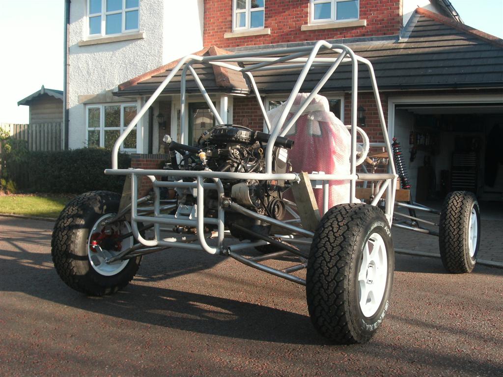
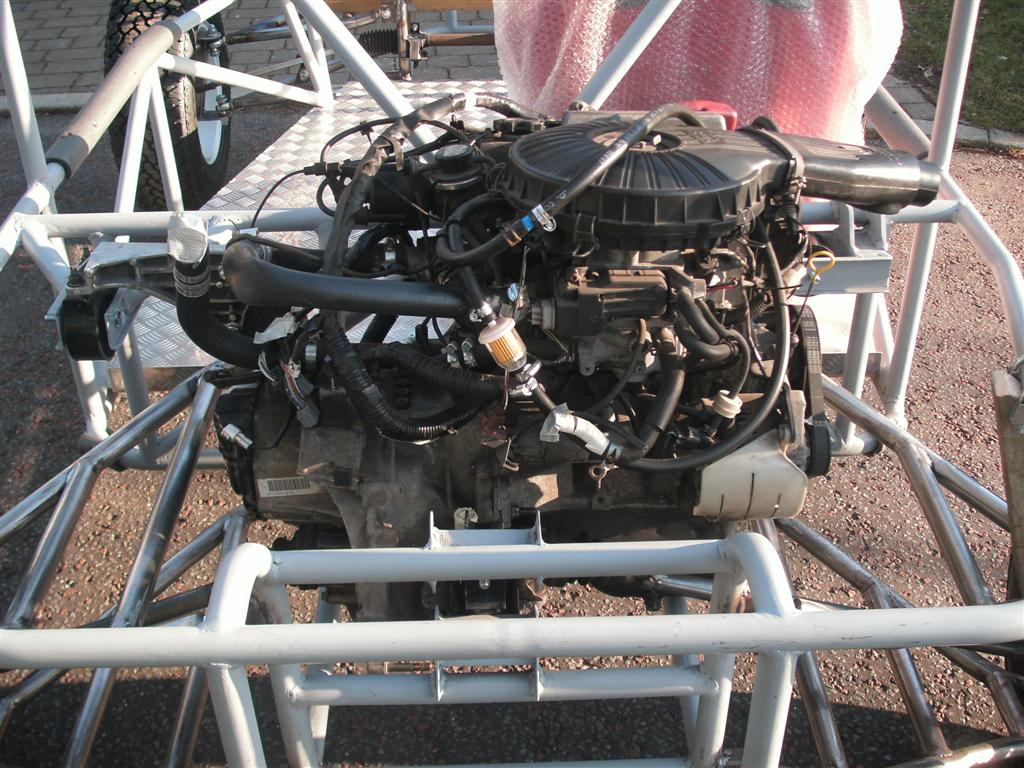
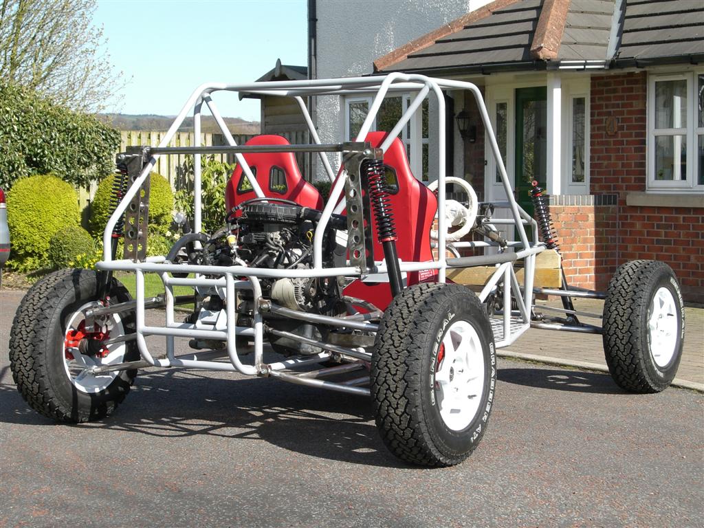
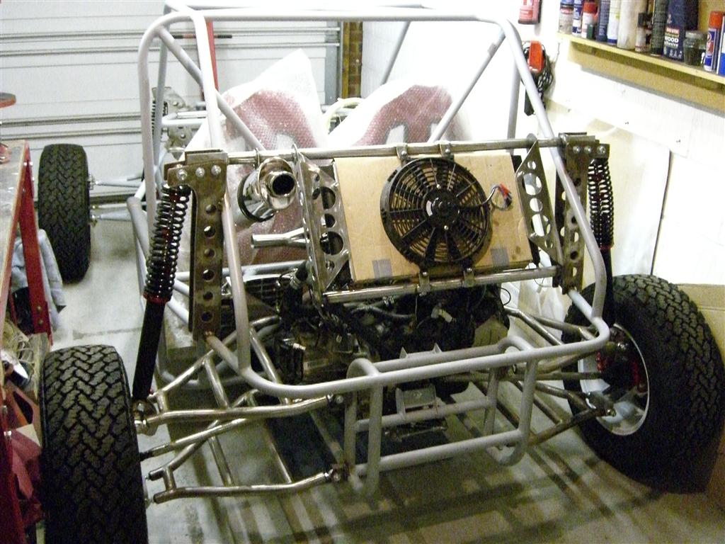
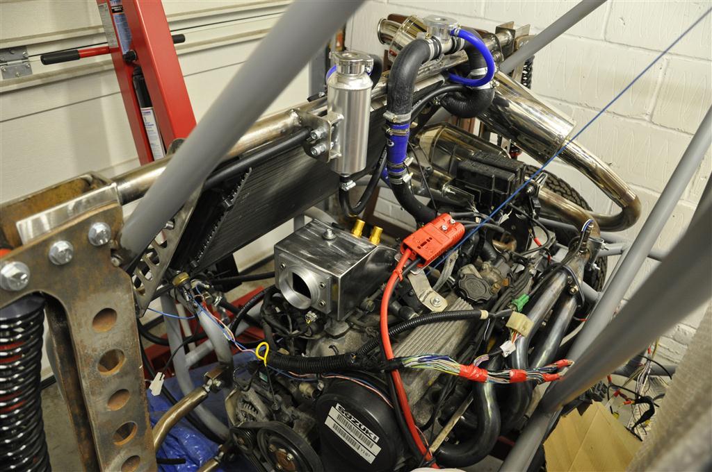
Hi everyone, New to the forum but did say I would post some photos of the buggy build so far, so here goes!!, I still have a long way to go but the project is going well so far, without too many major issues (those will come when I try to get it registered for road use). The buggy has been designed by myself (and a good bit of CAD software) and is powered by a suzuki swift engine and box.

Anyway I have a LOT of build pics over on my build site but here are a few to get you started :-

Day 1 280 feet of 1.25" (32mm if your in the UK) 2mm wall ERW tube - it dosent look much once its chopped up!
Image

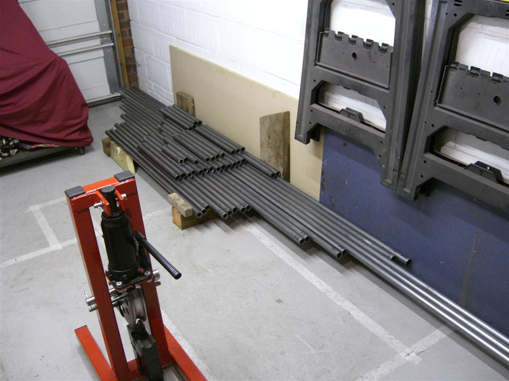
Majority of chassis parts bent to correct angle with the homemade tube bender:-
Image

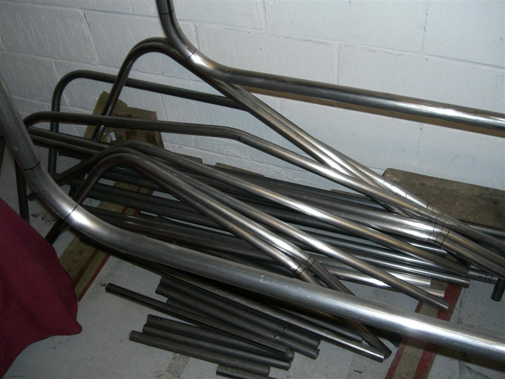
Start of the lower chassis section:-
Image

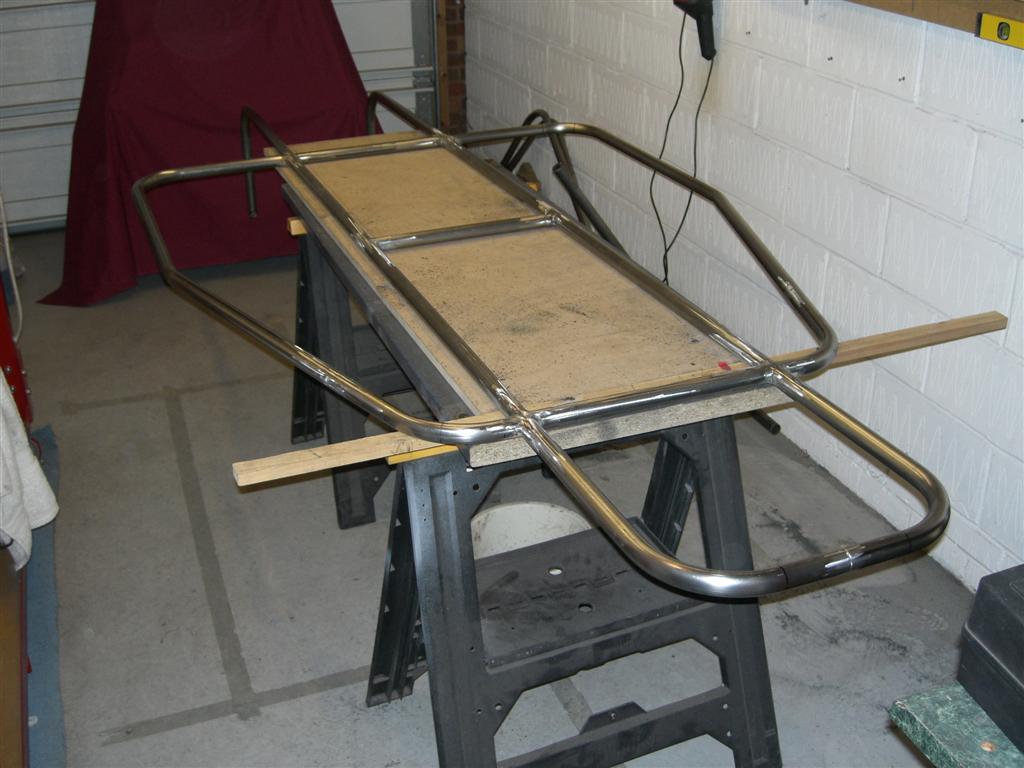
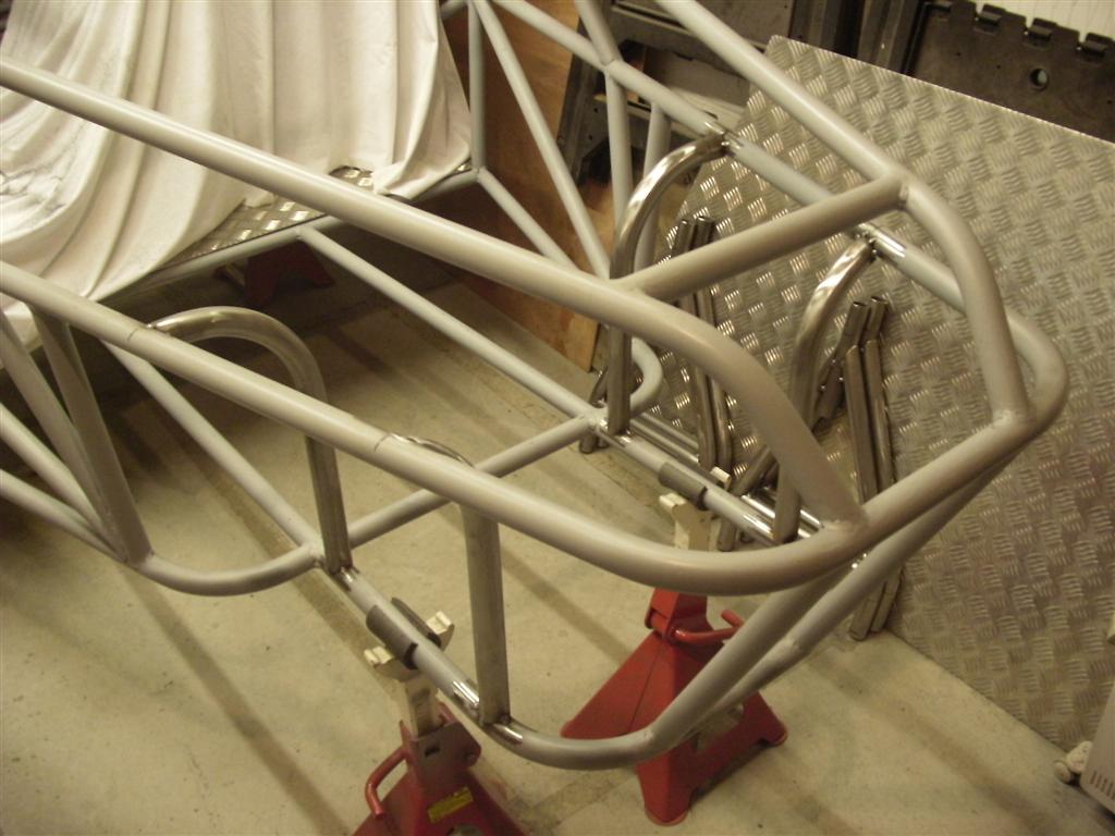
Chassis main roll over bar and rear cage:-
Image

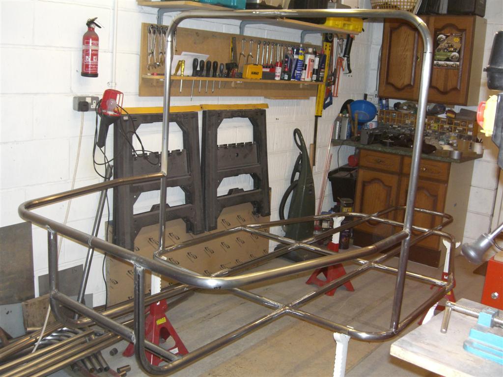
Chassis midsection and upper roll cage:-
Image

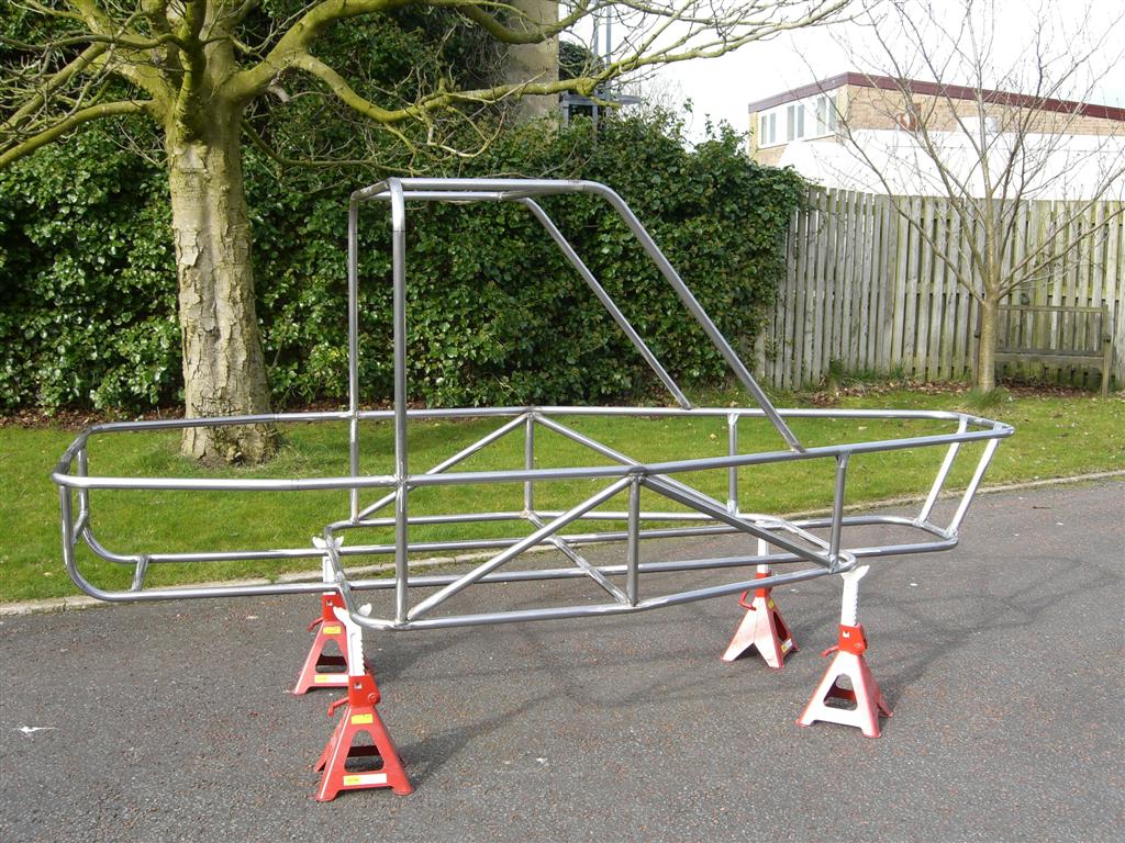
Chassis Upper section in place - starting to look right :-
Image

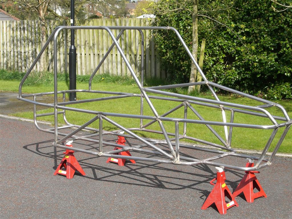
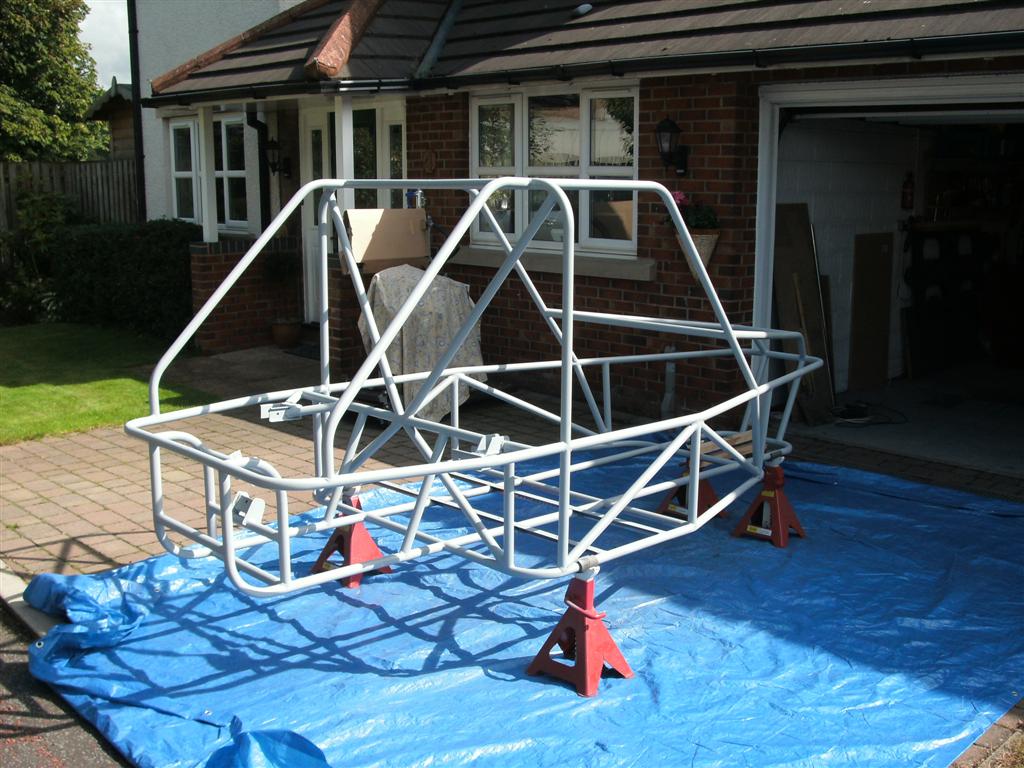
chassis with diagonals and engine mounts in place (and a bit of undercoat):-
Image

Here is a quick video:-
YouTube - Ultralite Buggy Construction Video No. 1

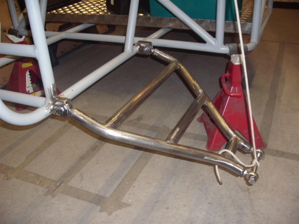
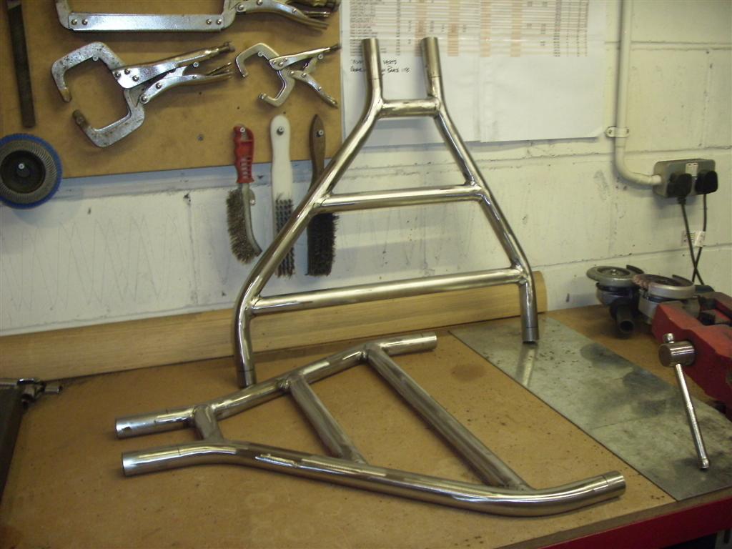
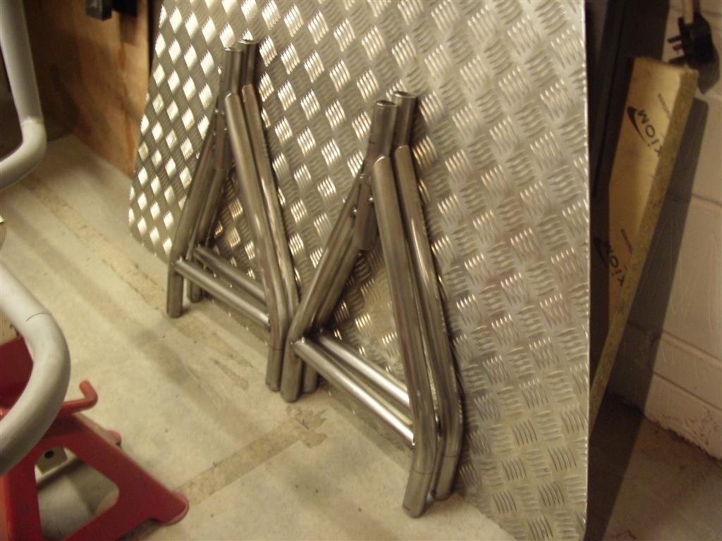
At it with the pipe bender again these 8 bits are the sides of the suspension A arms :-
Image

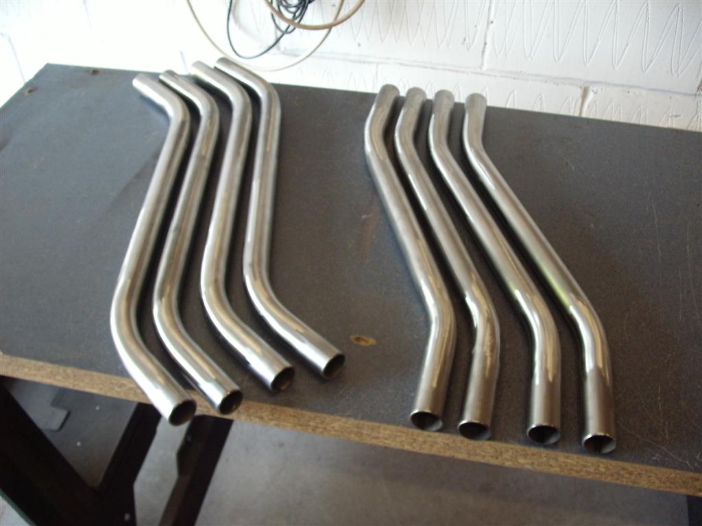
The jig to ensure all the arms are the same and repeatable :-
Image

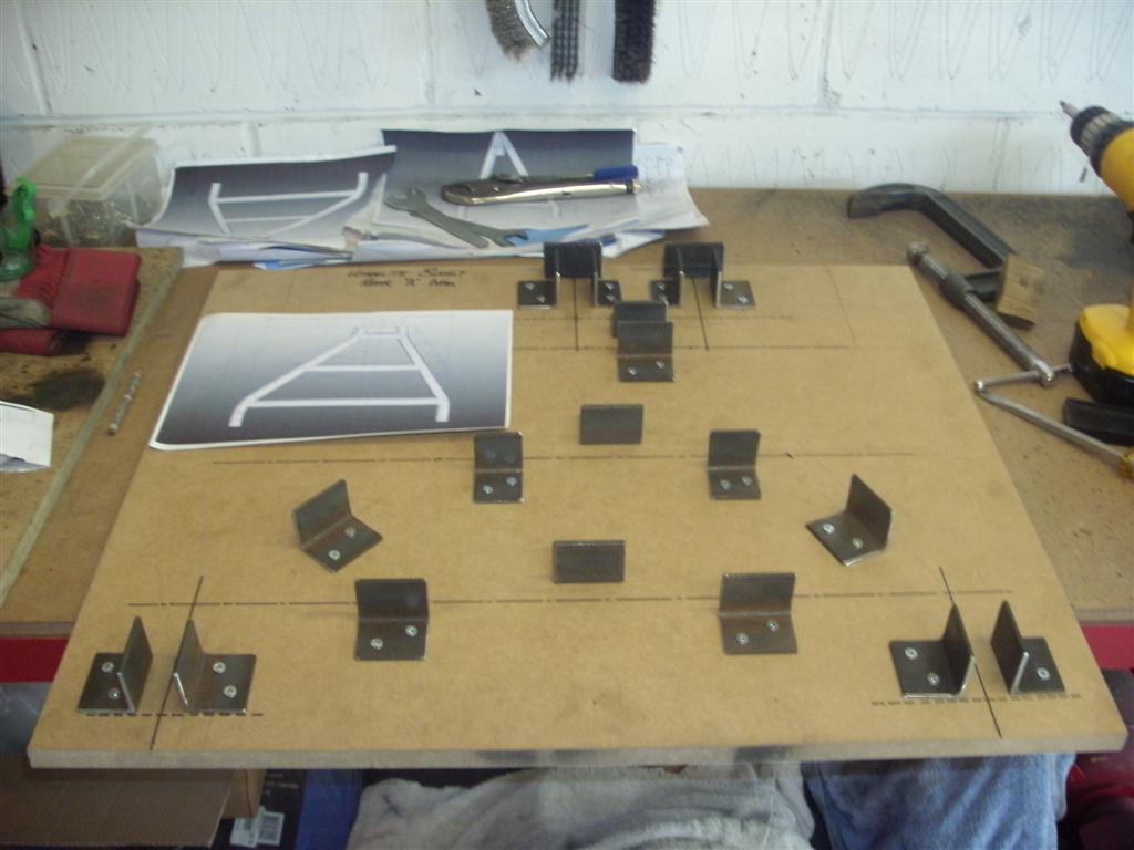
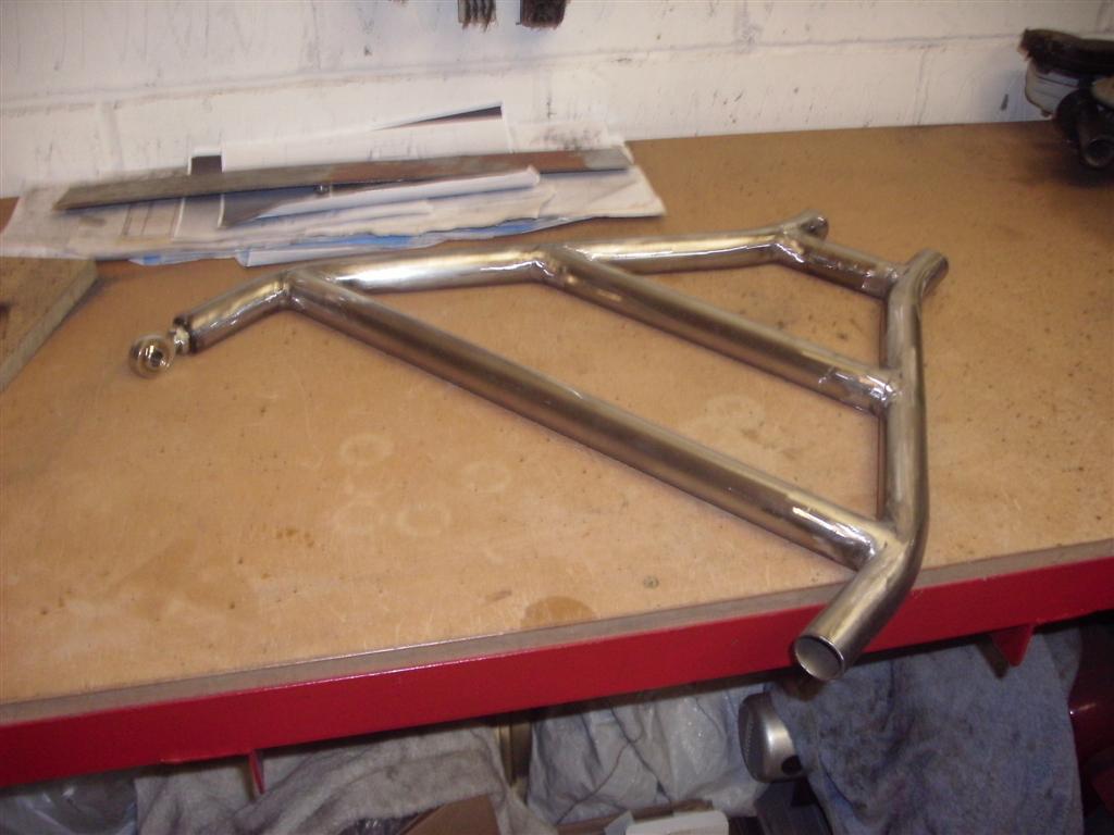
finished arm with a single rose joint in:-
Image

Both rear arms for one side mounted to the hub:-
Image

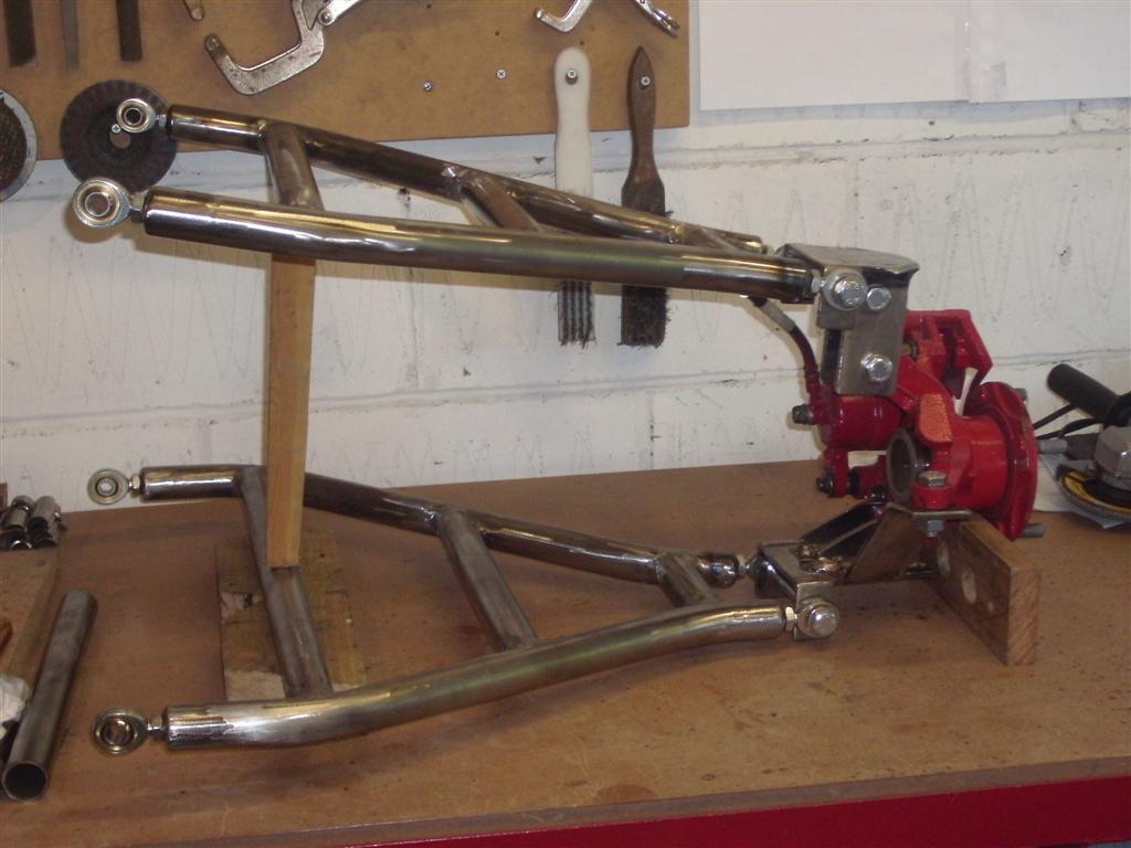
arms and hub hung in place at the back of the chassis:-
Image

First arm mounted correctly :-
Image

Final two rear suspension wishbones / A arms they need final trimming to length (note black lines on tube ends:
Image

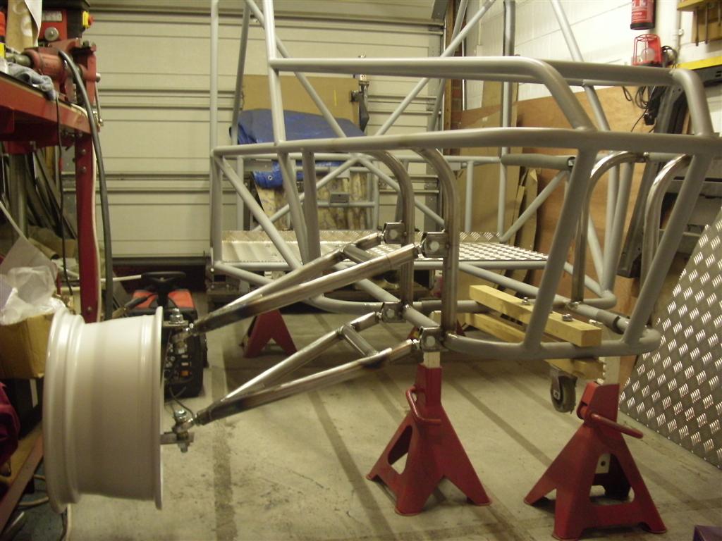
A couple of shots of the rear suspension in place:
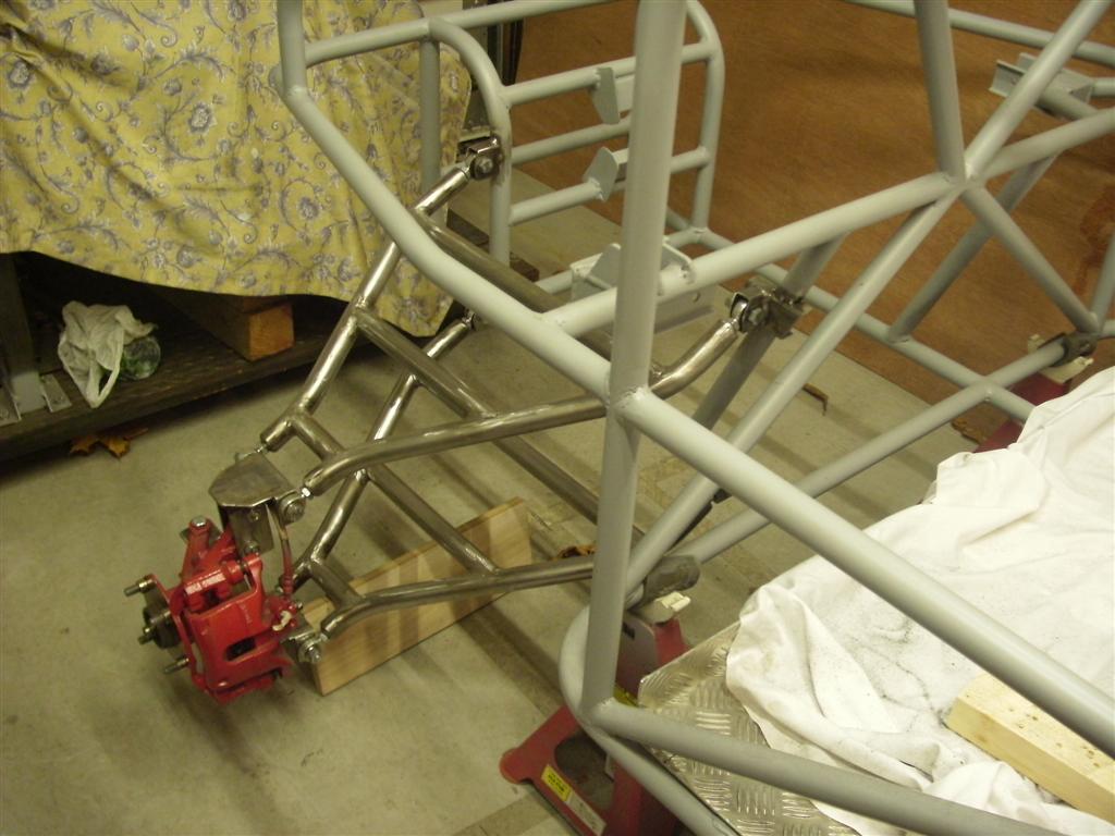
Image

and another:
Image

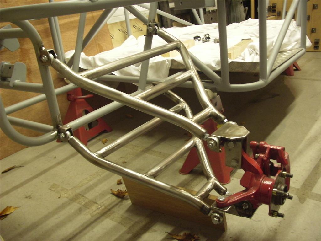
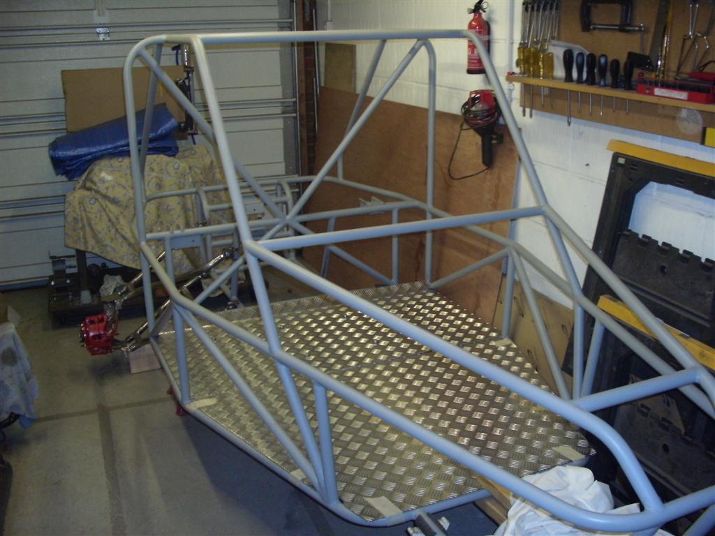
And finaly a shot of the chassis with rear arms in place and new alloy floor:
Image

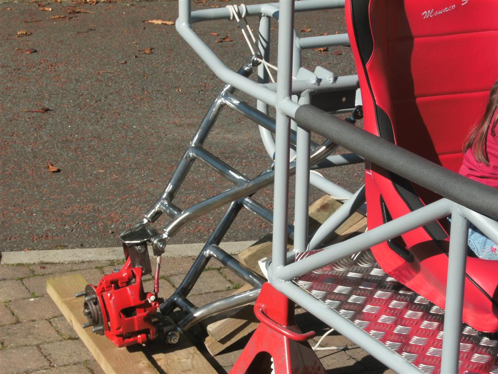
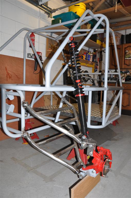
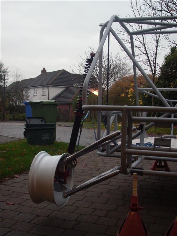
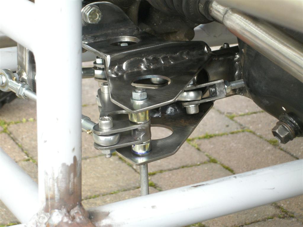
View of rear suspension showing shock location and new hub top mount (lower mount finished and now in primer-
Image

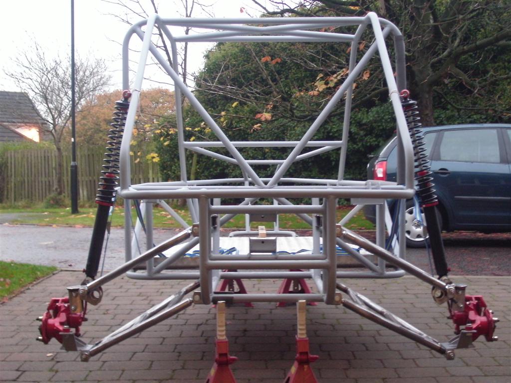
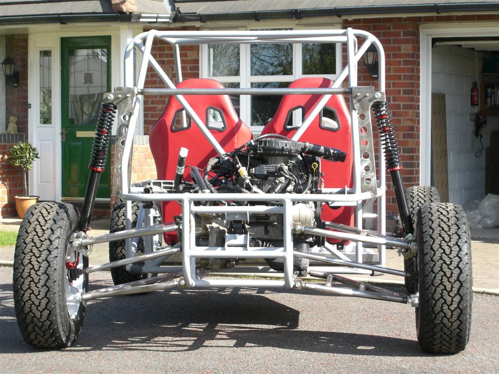
View from rear showing all suspension and shocks (shock upper mounting hoops not done yet)
Image

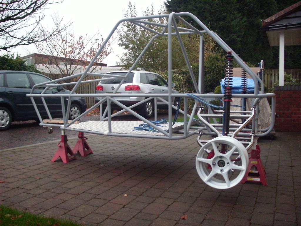
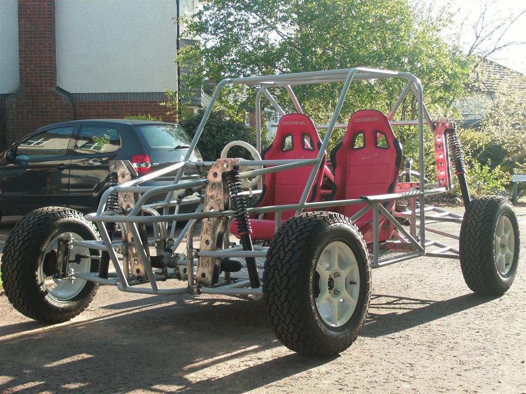
Side view with one of the new rims bolted on
Image

Rear view with rim
Image

the 4 front arms built (but not finished quite yet:
Image

And the front verticals in place ready for the suspension:
Image

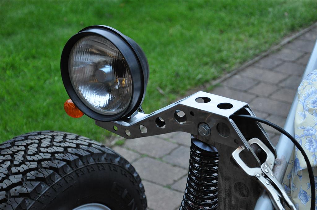
Been busy again, rough fitted at the moment but you get the idea :)
Image
And another shot of the front suspension -
Image

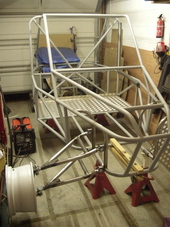
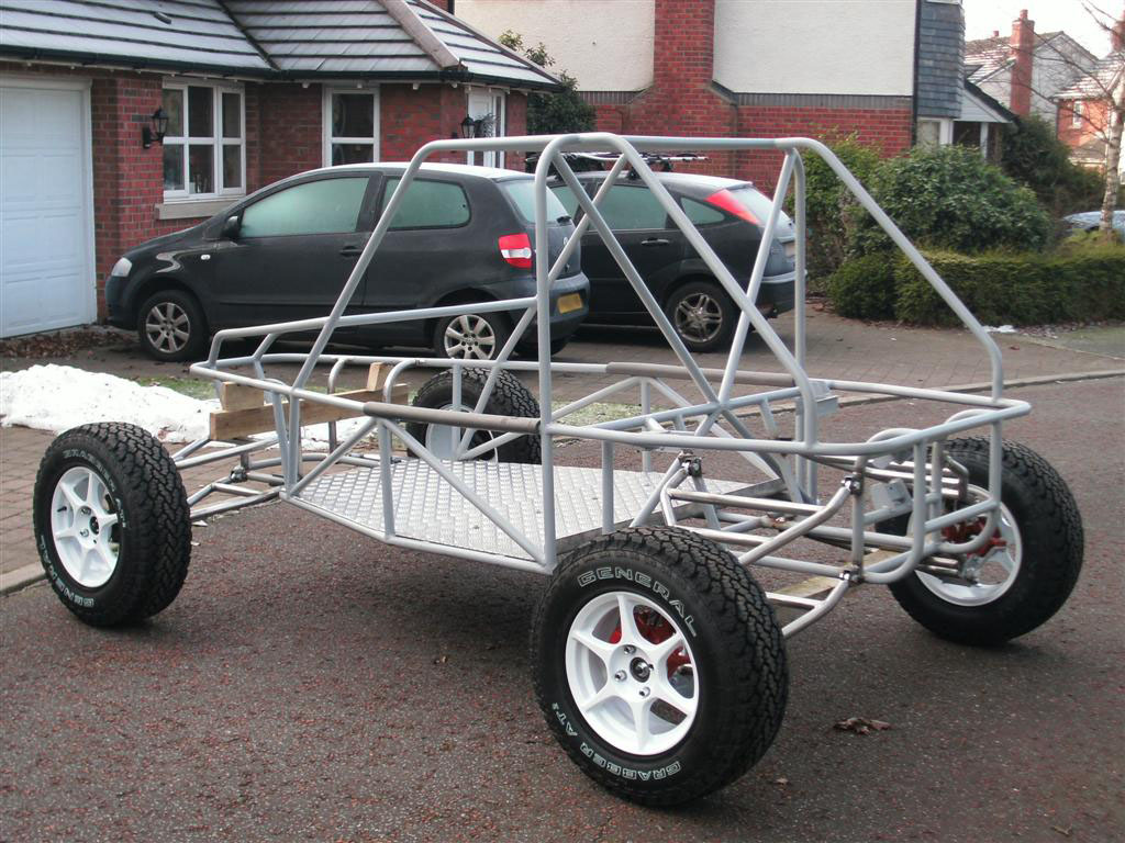
Picked up the tyres (General Grabber AT2 225/70/15), so I thought I'd put the rear suspension back together (as its easier to roll it out) as you can see its a tight fit in the garage now [smilie=ecstatic.gi:
Image

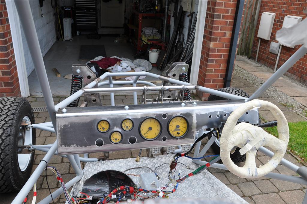
Well I wanted to get the buggy to a rolling chassis stage before the end of the year - and I made it!! - with only a few hours to spare (Finished new years eve 18:00 (2010) - in the dark!!) didnt get much chance to photo anything at the time apart from the tight fit in the garage!!

See what I mean....
Image

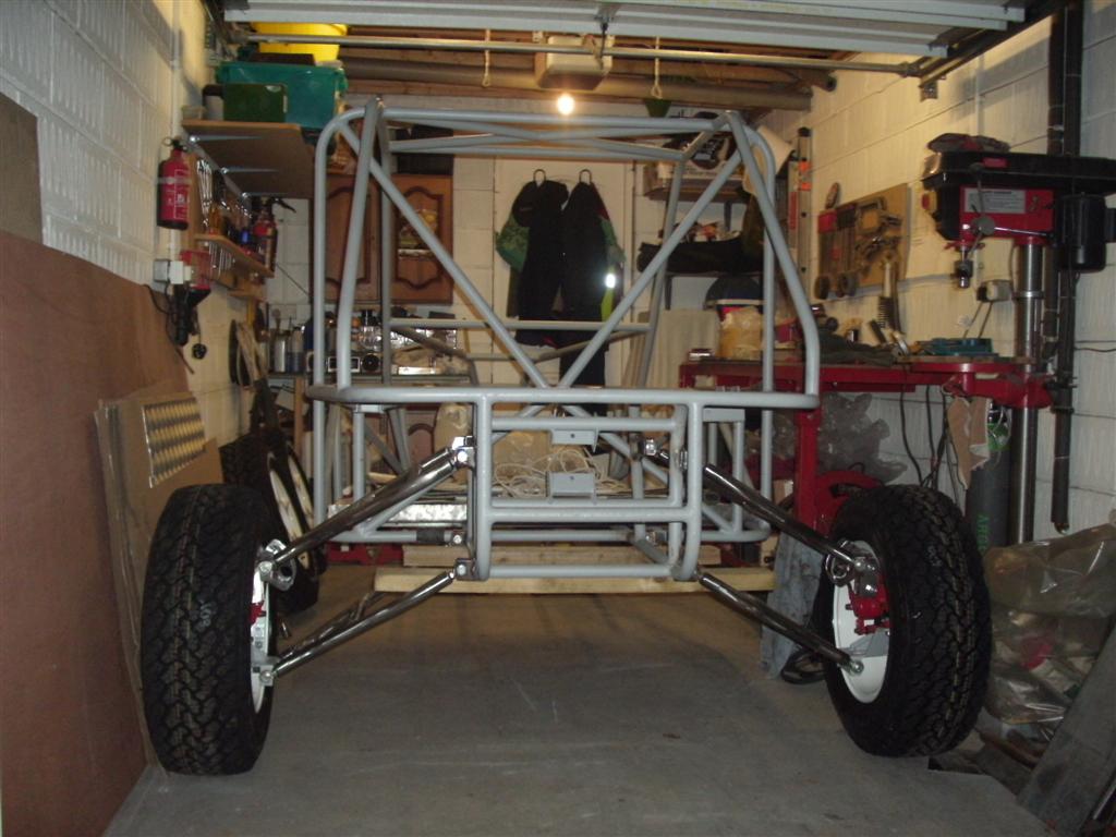
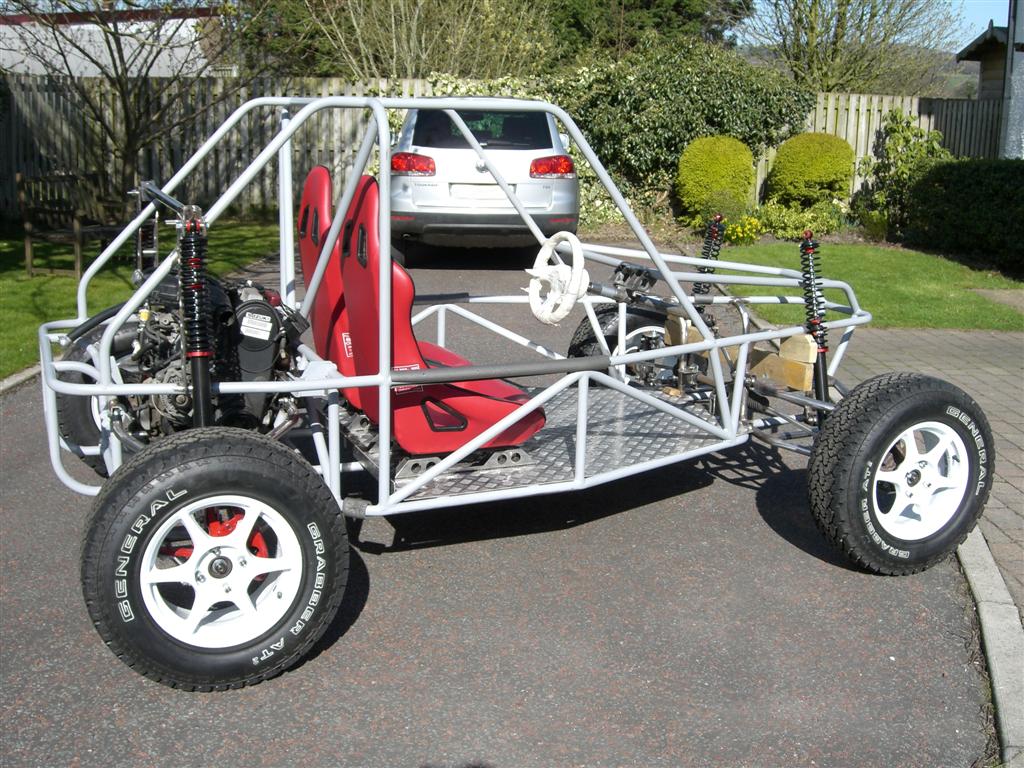
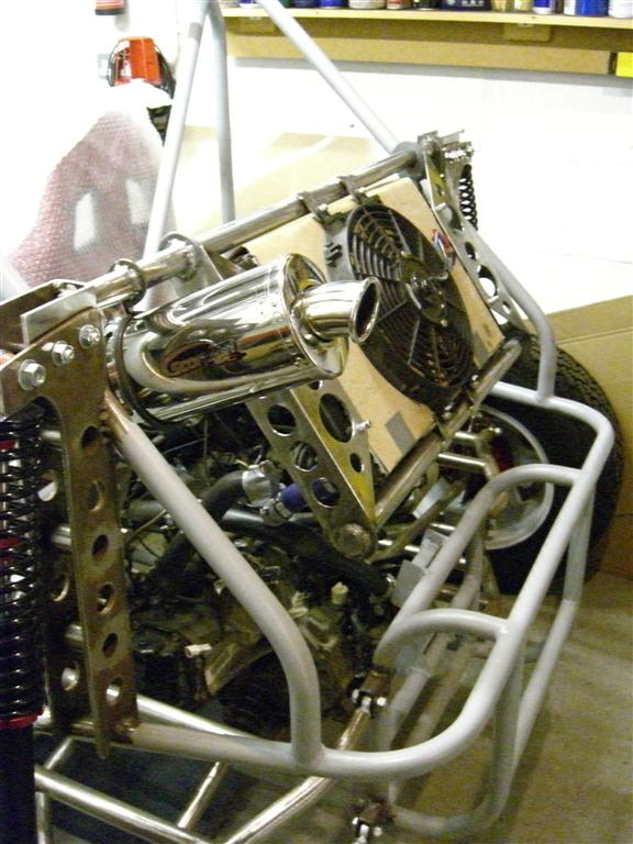
The next morning managed to take a few more shots here's a few:-
Image

Image

Image

Image

Image

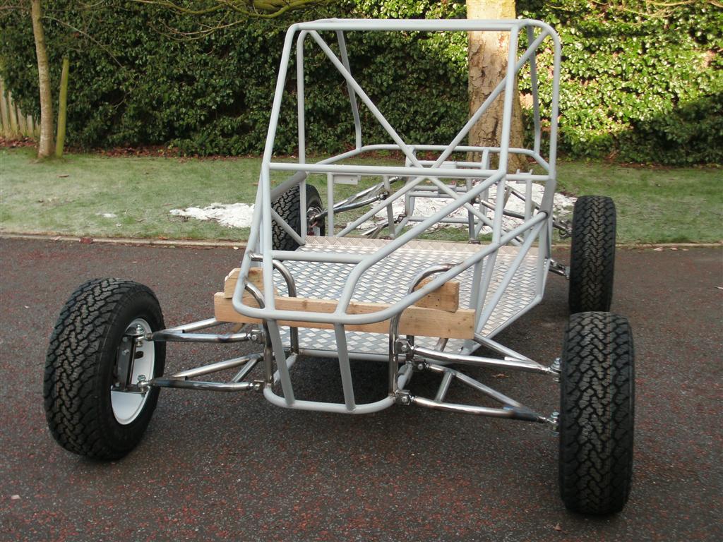
Still loads to do, like add the double shear to the front hub adaptors, sort out the rear shock mounts after checking the movement on the drive shafts etc...etc...etc...

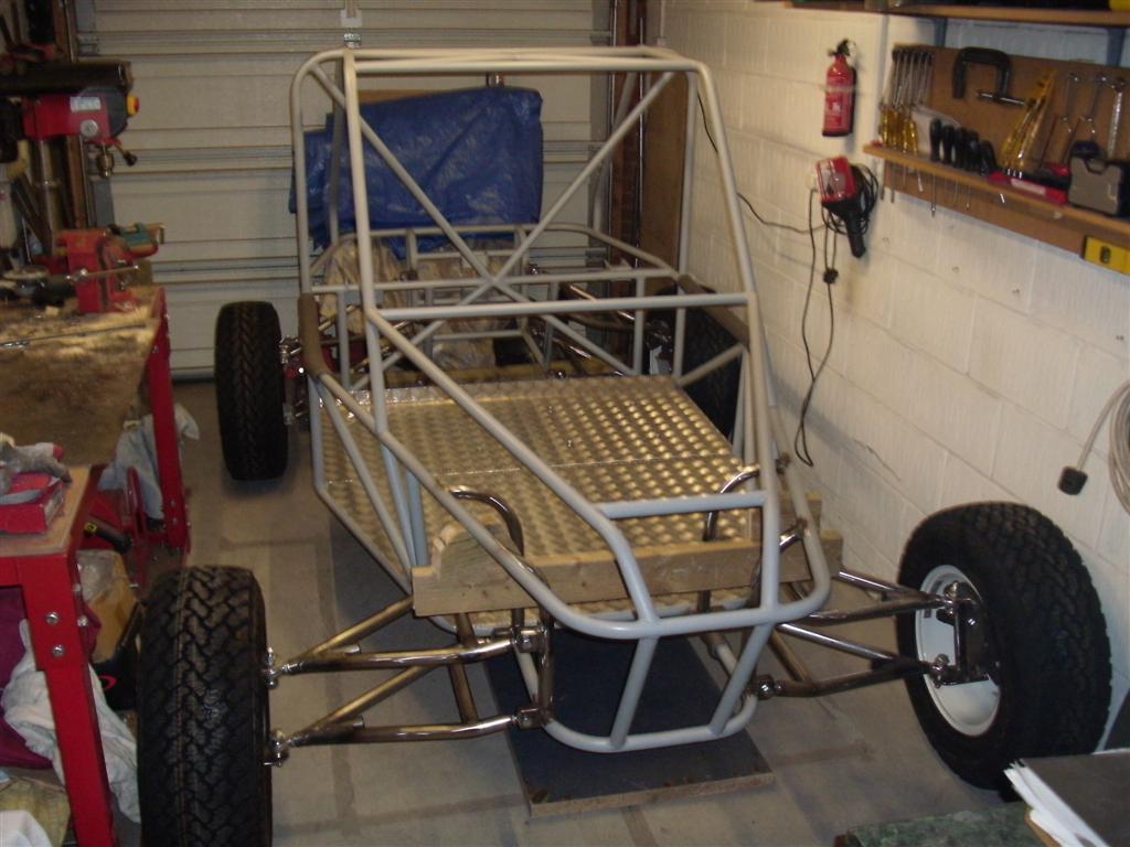
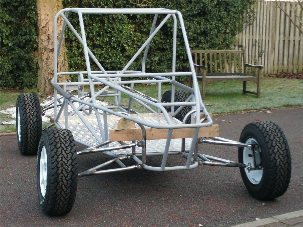
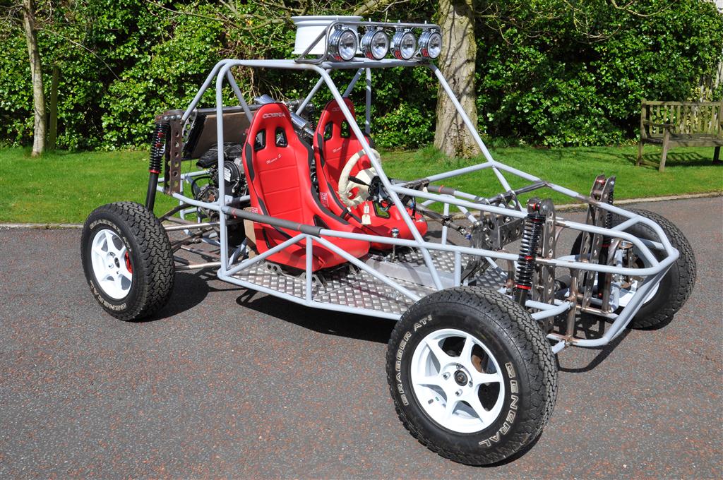
Its a nice sunny day so thought I would take a few progress shots,
Image

Image

Image

Image

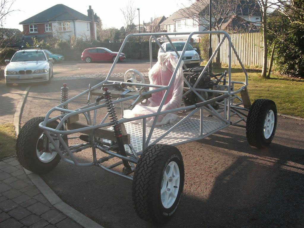
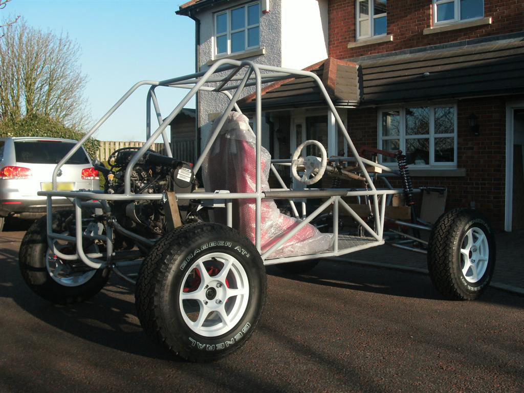
And then I put her back in the garage (taken the following day after I put the proper temp driveshafts in!! (the ones in the pics above were only to get the correct length!!
Image

And here is another construction video:-

YouTube - Ultralite Buggy Construction Video No. 2


And yes I know its called construction video no. 2 and I say its the third video... but the first vid i did on youtube was of the engine running on the stand I built for it - search for videos from TheBuggyBuilder and youll find it - thats if your really bored with nothing better to do that is!!

rear suspension mounts prior to fitting to the chassis:-
Image

And a few once fitted (and a second one built and fitted) also shows new seat mounts and steering column mount (first of two)
Image

Image


Image

Image

front suspension is now sorted (apart from the correct spring rates which is why its so low on the pic :) )

Here ya go:-
Image

Still loads to do, working on fitting the MR2 gear change assembly and cables next I think then pedal assembly!!

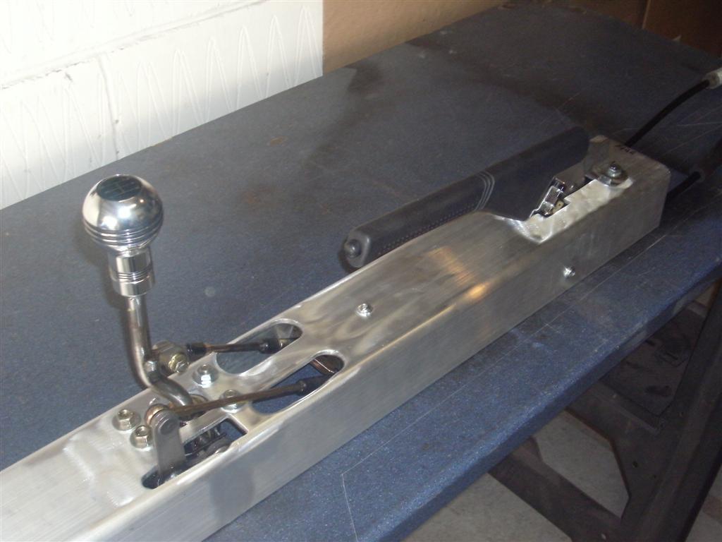
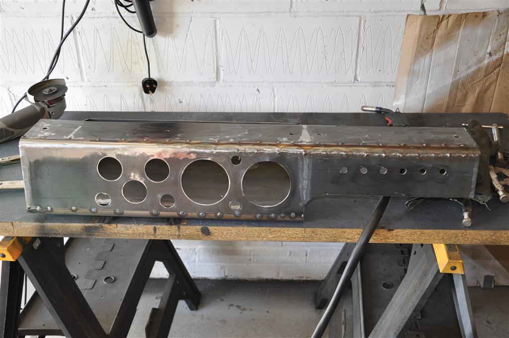
I have been busy in the garage recently building (and then scrapping and re-building) the gear shift assembly. Its using a Toyota MR2 Gear change assembly with MR2 Turbo Cables (soon to changed for custom units attached to a fabricated shifter assembly at the rear of the vehicle, so here are a few pics;

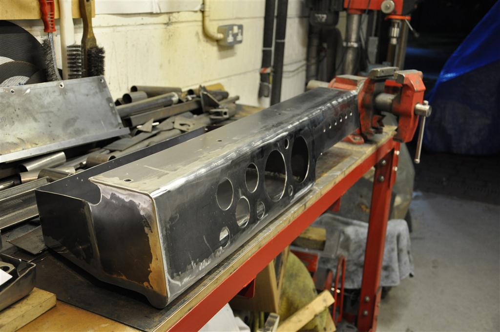
Alloy section used to house handbrake and gear shift assembly, cables atttached but layed onto to measure up!
Image

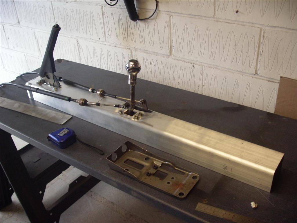
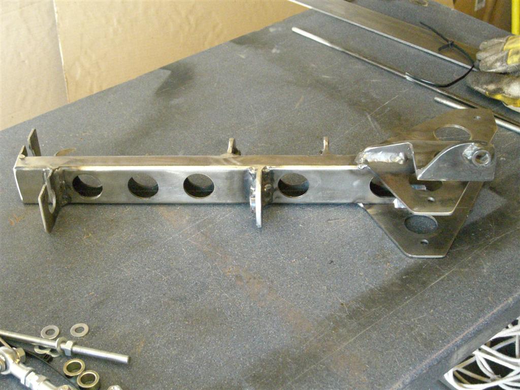
Cut outs done for mounting cables through
Image

Working version of the selector mechanism bare
Image

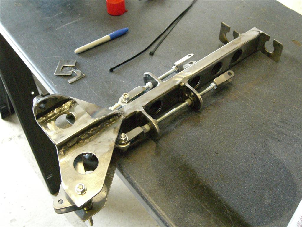
Mechanism with push rods and cranks fitted (extended threaded rod to be swapped out)
Image

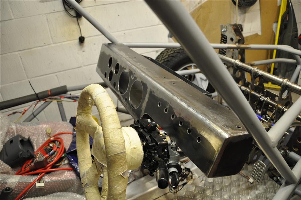
Fitted in position at the back of the buggy! (Again the extended threaded rod is to be swapped out with correct length bolts)
Image

Image

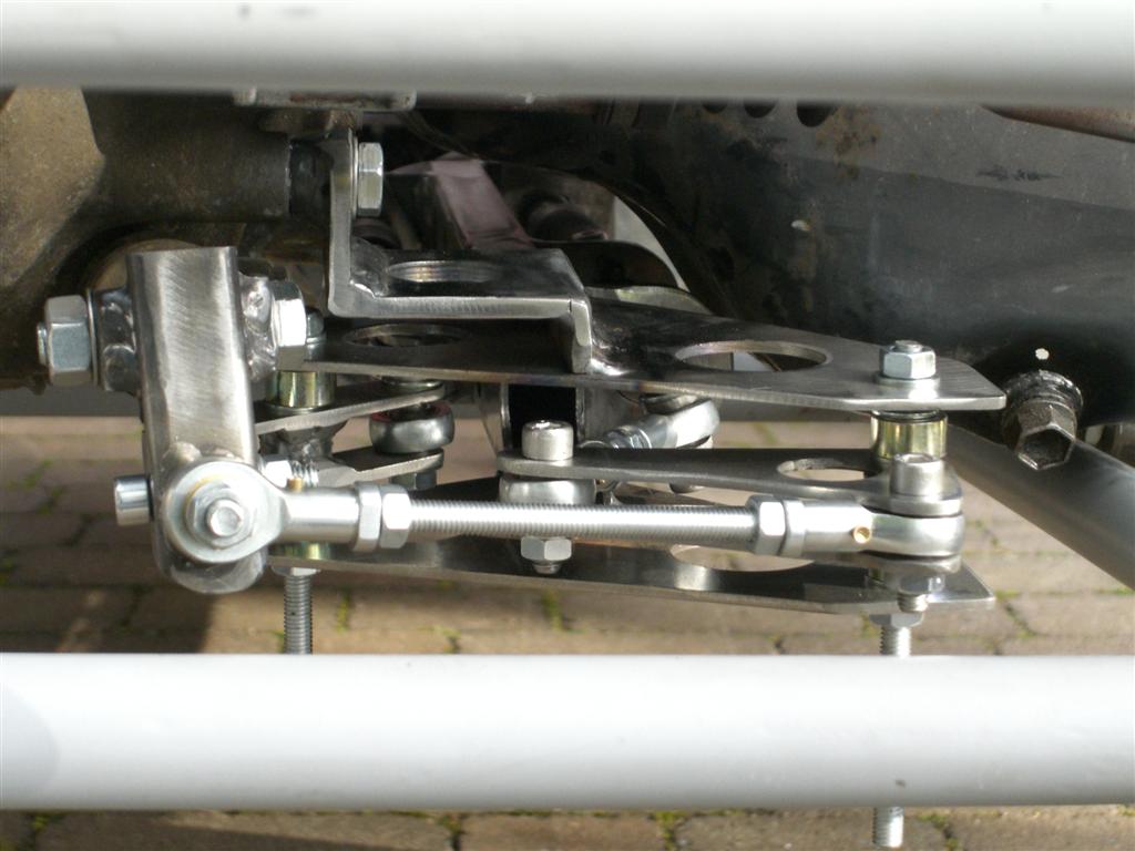
A lot of work went into getting this correct, it was surprising just how much work was needed just to find out how big the cross gate crank needed to be! Anyway it works like a dream now, just enough movement across the gate and a good notchy click as it goes into each gear, overall I'm very happy :D

I am now working on the pedal assembly which is a hung assembly - as a floor mounted one to me didnt feel as good - anyway its another scratch build job (should'nt take as long as the gear change )

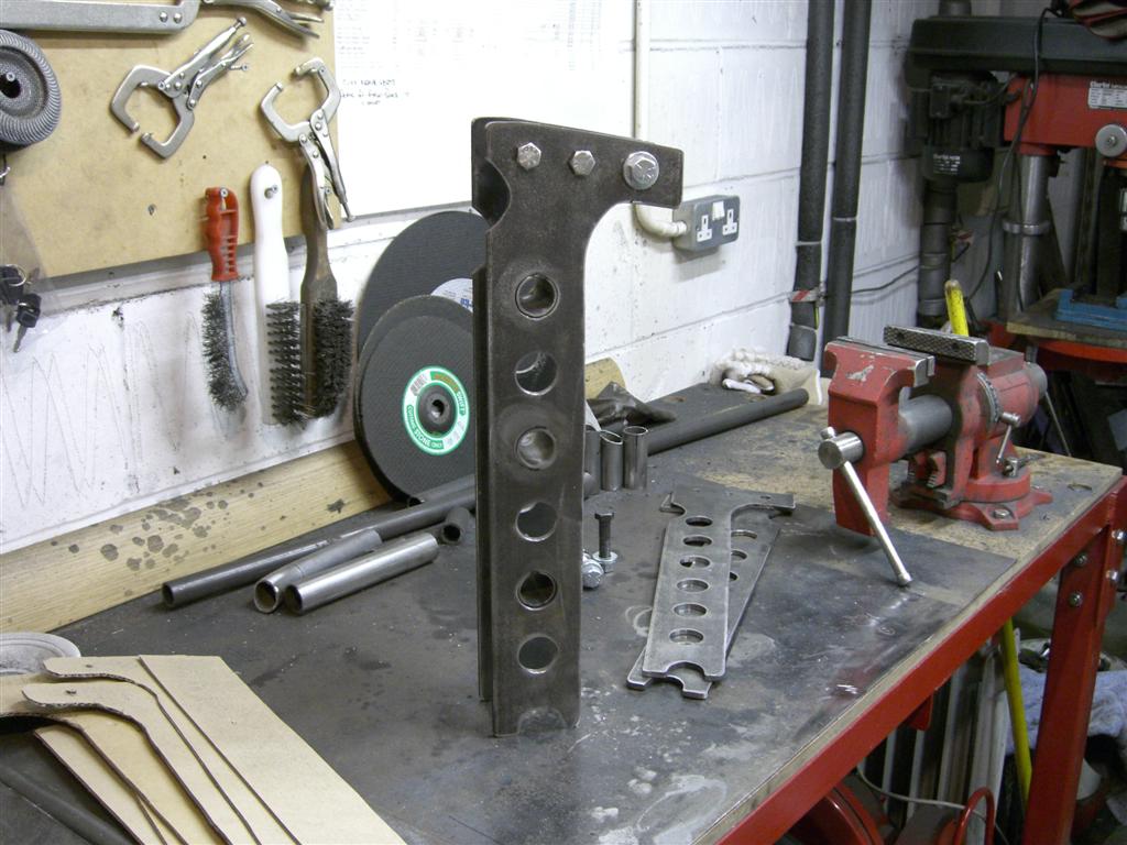
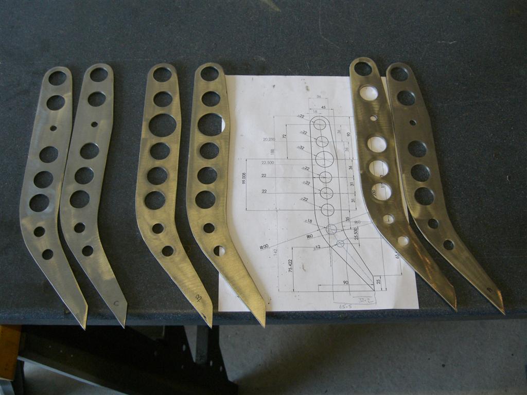
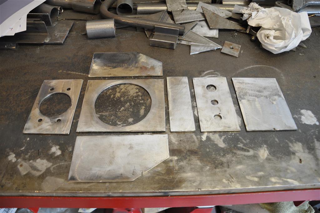
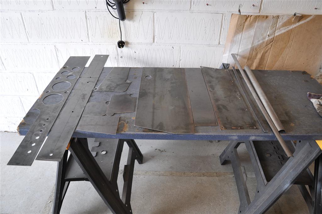
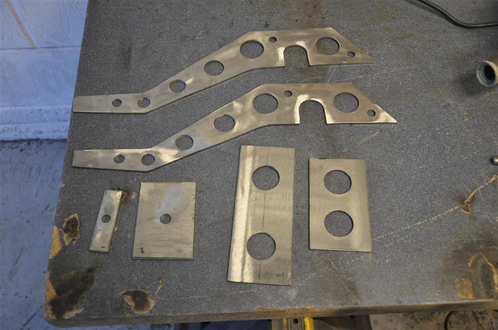
Got the pedal assembly designed and started cutting out the pedals, so here are a few progress shots:

Blanks rough cut-
Image

Blanks drilled and cleaned up:
Image

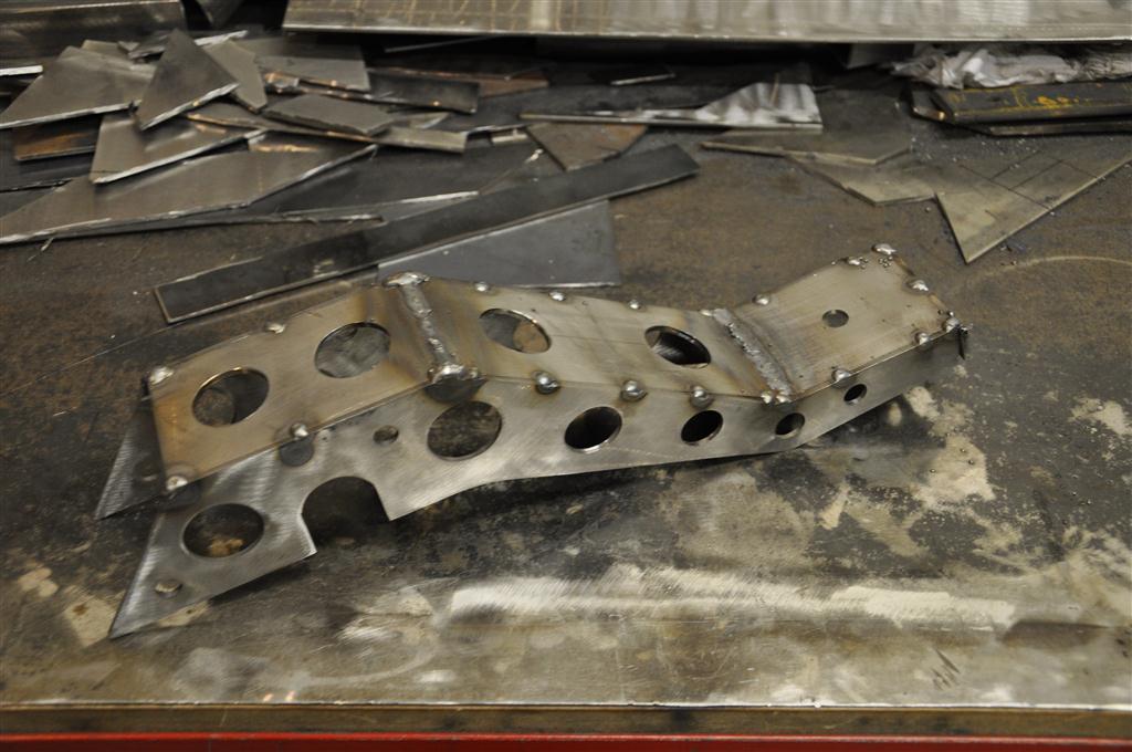
And finally welded together;
Image

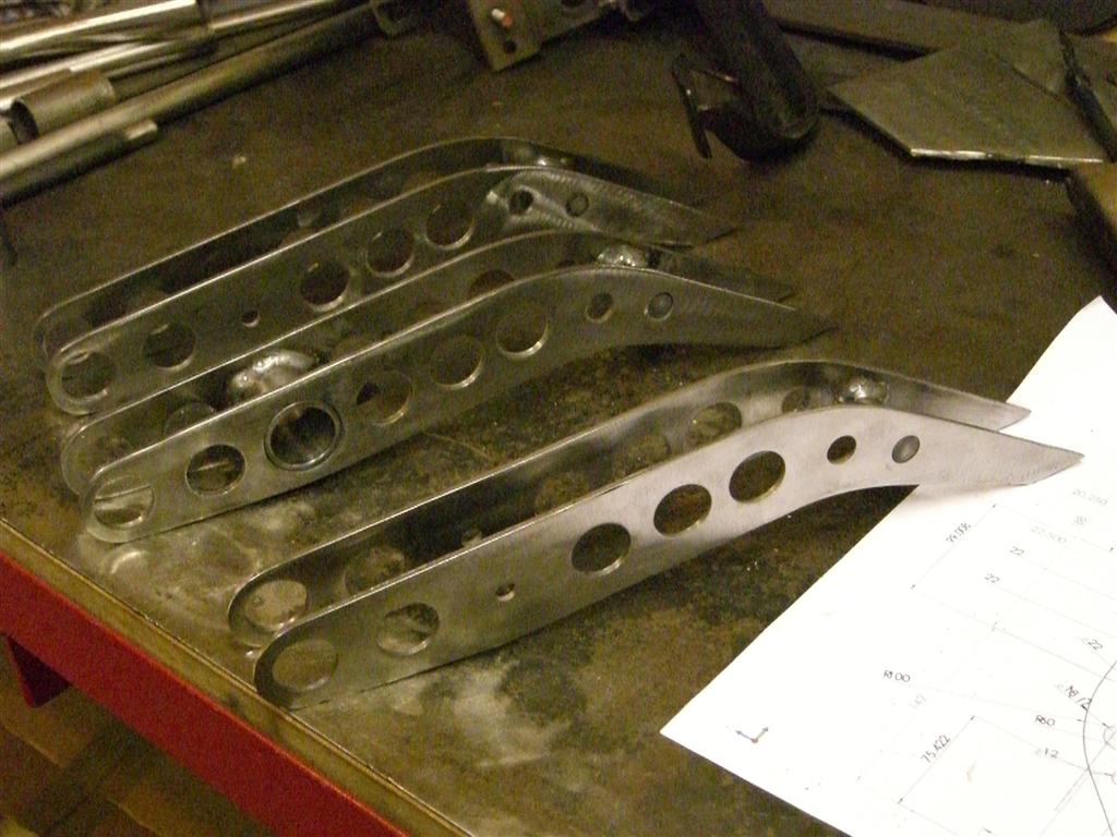
Just need to weld the spindle tubes into the top of each and add the foot pedal mount at the bottom of each now and crack on with rest of the assembly :)

Finished Pedals
Image

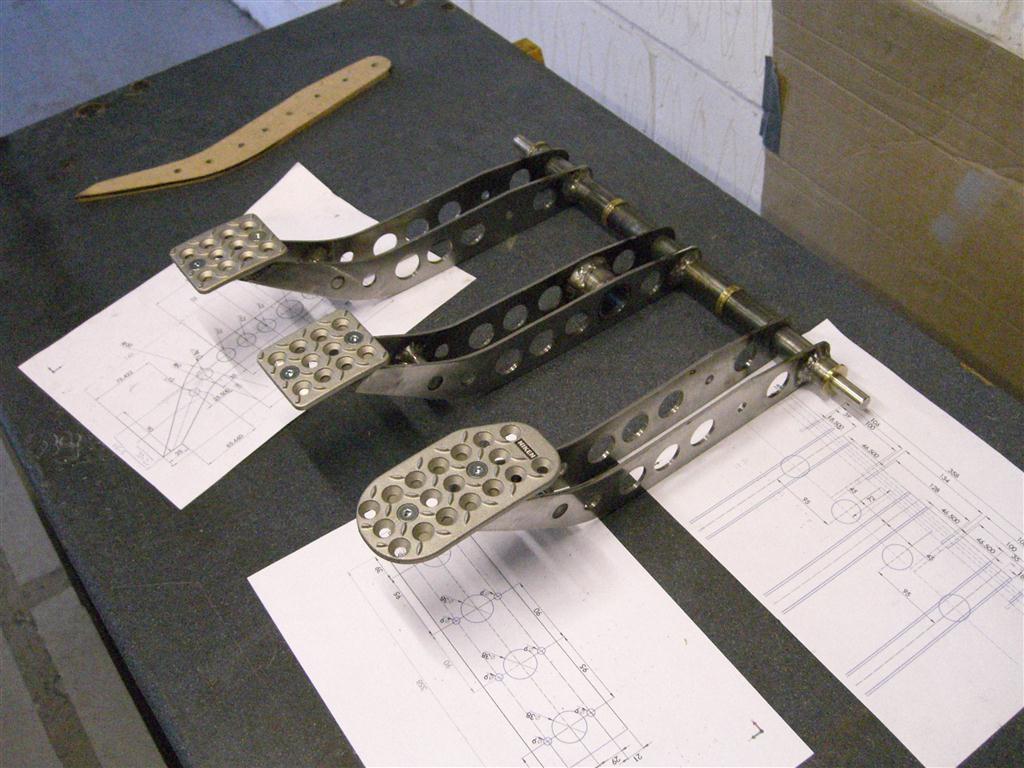
And the mounting for the pedals
Image
Image

more work on the pedal assembly had to scrap the backplate i originally did as the two master cylinders for the brake were set at what I thought was the correct width but after assembly and testing the balance bar kept locking / binding so off came the plate and a new one made and everything welded back together.

This is what it looks like now with spring return bar and pedal stop in place-
Image

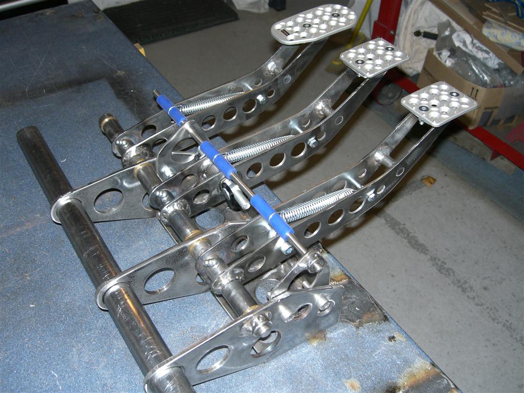
And finally hung in the buggy - its a snug fit :D
Image

Author:  ChaosMS [ Wed Jul 13, 2011 1:11 pm ]
Post subject:  Re: Suzuki 1000cc Geo Metro / Swift Powered road legal buggy

Next thing to sort is the Exhaust system!!

New Manifold for the G10 engine

Image
Standard manifold on the right ;) just using tape to hold the primarys together for the moment

And here is one with the manifold in place;
Image

Just the merge collector to build now (and weld it all together)

Finished (almost) off the manifold tonight and took a couple of shots so here ya go!
Image

Image

Still got to weld a nut on to hold the O2 sensor after the merge collector and give it a good coat of clear high temp paint but im happy with it so far! :cool:

Image
Radiator mount finished and fitted (Rad core is covered in cardboard at the mo ;)

Image
close shot showing back box in place and side view of the rad mount.

A quick video update:-

YouTube - Buggy Construction Video No. 3

Anyway here is how she looks at the moment-
Image

Been busy making the new airbox and fitting the Induction / filter system so time for a quick update -here are a few pics!

Sheet metal parts cut out and drilled ready for assembly;
Image

Completed Airbox seam welded finished ready for paint;
Image

Fitted to Injection system;
Image

Induction pipework with silicon joiners and airfilter fitted;
Image

Induction system joiner shown fitted (but not clamped) to airbox;
Image

Been busy this weekend working on the dashboard here are a few pics

Dashboard panels cut out ready for assembly
Image
Panels tack welded together
Image
Fully welded and finished (just about)
Image
And with the dash dropped into position
Image

Still have the bolt down lid to finish off but I'm happy with the dash so far!


It was like Christmas at my house today! - the fuel tank that was made to my drawings by ProAlloy (And they did a fantastic job I reckon) and the gauges that were built for my engine by ETB instruments arrived!!! here are a couple of pics;
Image
Fuel tank showing breather/feed/return ports filler and Sender port (under the tape in the middle) and the turned pot at the bottom is the fuel sump!
Image
And the matching set of gauges (Rev counter built specifically to switch between 3 and 4 cylinders.
I dropped the gauges into the dash for a quick pic! so here you go -
Image

Well got a bit more done this weekend decided to fit the front lamps so fabbed up these mental lamp brackets! due to the narrow nose and long suspension arms the lamp brackets had to lower the main lamp (To comply with the 1200mm max height from floor IVA rule) and push it out towards the wheel quite a long way (To comply with the 400mm to outside edge of vehicle IVA rule) Anyway here are a few pics

Plate cut and drilled ready for welding -
Image

Tacked together -
Image

One finished and on (clamped in position) -
Image

Both finished and clamped on -
Image

I think they look a little mental, but hey so does the rest eh!!

Lamps are a 7 inch rubber cased unit and the indicators are rubber stalked bike type!


Well thats the build so far as that lot has taken quite a while to do!!

What do you think??? :D

Author:  ljkart [ Wed Jul 13, 2011 1:13 pm ]
Post subject:  Re: Suzuki 1000cc Geo Metro / Swift Powered road legal buggy

awesome work!!

Author:  ChaosMS [ Wed Jul 13, 2011 1:20 pm ]
Post subject:  Re: Suzuki 1000cc Geo Metro / Swift Powered road legal buggy

EJ Mac & ljkart - Thanks very much i need to take some more photos and ive just noticed the youtube links arnt working so im just going to sort that now :D

Author:  Norman82 [ Wed Jul 13, 2011 4:26 pm ]
Post subject:  Re: Suzuki 1000cc Geo Metro / Swift Powered road legal buggy

Man that thing is super nice.Very good work.actually fantastic work!!!!!!

Author:  karl [ Wed Jul 13, 2011 6:22 pm ]
Post subject:  Re: Suzuki 1000cc Geo Metro / Swift Powered road legal buggy

Wow! Do you have a CNC plasma cutter at your disposal?
That is some clean work.

Author:  ChaosMS [ Wed Jul 13, 2011 6:42 pm ]
Post subject:  Re: Suzuki 1000cc Geo Metro / Swift Powered road legal buggy

Norman82 - thanks for the comments much appreciated :D

karl - I WISH i had a CNC plasma cutter, nope everything you see here has been built cut and shaped with an angle grinder (2 grinders actually so I dont need to keep swapping disks) lots of holesaws (various sizes) all the tube has been bent with my own tube bender which I also built!!

If I was to do it again I would have a lot of the parts cut by laser or water I think, it would speed things up and would be quite easy to do as every part is modelled in CAD

Cheers

Author:  Panzer [ Wed Jul 13, 2011 6:58 pm ]
Post subject:  Re: Suzuki 1000cc Geo Metro / Swift Powered road legal buggy

Wow! great job!! =D> =D>

but your steering wheel is on the wrong side #-o ....just teasing :D

Author:  crispin [ Wed Jul 13, 2011 7:25 pm ]
Post subject:  Re: Suzuki 1000cc Geo Metro / Swift Powered road legal buggy

Can you tell me what you used for your axle and Hub Disc?
Are those Suzuki Axles?
Great build!

Author:  JLJ [ Wed Jul 13, 2011 7:27 pm ]
Post subject:  Re: Suzuki 1000cc Geo Metro / Swift Powered road legal buggy

You are a very talented fabricator, your attention to detail is amazing. Are you planning to cover up your work with body panels or is it to stay open?

Author:  justwonderinginky [ Wed Jul 13, 2011 9:09 pm ]
Post subject:  Re: Suzuki 1000cc Geo Metro / Swift Powered road legal buggy

that is some wonderful work... very impressive... question do you happen to have a set of plans for your tubing bender?

Author:  GMANLV [ Wed Jul 13, 2011 9:59 pm ]
Post subject:  Re: Suzuki 1000cc Geo Metro / Swift Powered road legal buggy

That's some really nice work. Loads of patience using angle grinders and hole saws. =D>

Greg

Author:  TeamHog [ Wed Jul 13, 2011 10:15 pm ]
Post subject:  Re: Suzuki 1000cc Geo Metro / Swift Powered road legal buggy

That's a great looking buggy.
Is this your plan or something you purchased.
As other's have said the detail is amazing.
The pictures and quality are amazing.

Author:  whatharleyold [ Wed Jul 13, 2011 10:44 pm ]
Post subject:  Re: Suzuki 1000cc Geo Metro / Swift Powered road legal buggy

Very Cool Great Work wow

Author:  CookieMonster [ Wed Jul 13, 2011 10:53 pm ]
Post subject:  Re: Suzuki 1000cc Geo Metro / Swift Powered road legal buggy

I'm speechless. This makes my work look like child's play.
Excellent. I'm thinking about tinkering with bending tube for my next small project. May need some pointers.

Author:  tjfast55 [ Thu Jul 14, 2011 1:37 am ]
Post subject:  Re: Suzuki 1000cc Geo Metro / Swift Powered road legal buggy

that is completely unreal work. Would you consider making another intake box like the one you built? I'm in dire need of one for my swap and fell in love with yours. I'm sure we could work out a good price for you do that.

Author:  grutz [ Thu Jul 14, 2011 10:38 am ]
Post subject:  Re: Suzuki 1000cc Geo Metro / Swift Powered road legal buggy

Off the charts awesome!

Author:  ChaosMS [ Thu Jul 14, 2011 11:43 am ]
Post subject:  Re: Suzuki 1000cc Geo Metro / Swift Powered road legal buggy

Firstly, WOW thanks everyone - all comments greatly appreciated :oops: :D

Crispin - yes those are stock Suzuki swift Front hubs and driveshafts on the rear of the buggy, soon to be fitted with vw golf mk3 calipers (so I have a handbrake), there are a second set of suzuki front hubs and calipers on the front with axle stubs in place to hold them together (same system used on the MGF to hold its hubs together) - the driveshafts are stock apart from being A LOT longer (I have extended them myself but I will be taking them to a professional company for strengthening and balancing)

JLJ - i will be making a fibreglass nose cone for it which will run smoothly and tightly to the shape of the tubing at the front and will run up to the windscreen (if it had one) area but it will be open down both sides and most of the rear (all the moving parts and hot parts on the engine will need to be covered where possible to comply with the road legal regulations) I will also be making cycle style wheel arches which will be mounted to the hubs for the front and rear, basically I will be leaving as much open as I can that does not cause me problems getting through the test!!

TeamHog - I designed and did the plans myself, the entire buggy was built up in a CAD/CAM package first, in fact when the steel tube arrived (all 280 feet of it) I cut ALL of it up into the parts needed for the chassis, numbered each one so it coresponded to my cutting list (also generated from the CAD/CAM software) and then bent all the tube as per the drawings (I had a excel spreadsheet that I set up with the distance along each tube where each bend should be and how many degrees each bend was, it was a worrying time I can tell you - but it all worked out and I have not had to recut any of the tubes for the chassis or suspension due to design error!!

Justwonderinginky - I based the tubing bender on a plan from ebay, I made a few modifications to the design but its a very simple design - the key component was the former which I had to import from Pro-Tools in the USA, it was the only place I could get a former head without buying a whole tube bending kit have a look at http://www.pro-tools.com 105 former heads- as for the plans for mine I dont have any I just modified the ones I got off ebay however all you really need is a basic drawing of the layout and how it was put together and you should be able to duplicate it easily! (check out the pictures of the tube bender in the gallery section of my project website at http://www.chaosmotorsport.com )

Cookiemonster - Happy to help where I can :D and thanks for the comments

tjfast35 - the airbox and intake are very easy to build, and cost next to nothing for the raw materials to build it, if you still have the large plastic pancake filter housing you need to strip all the rubber parts off it as your gonna need em! the main body is just a few bits of 3mm thick plate steel, If you like I can run off another drawing from the model of the buggy then you will have some drawings to work from, as for building it for you thats not an issue apart from the postage costs to you could be far higher than the cost of making the whole unit yourself!! (its very easy aslong as you have a grinder and a welder) the tube mounting flange and 72mm ID alloy tube came in a aftermarket induction kit and the silicone joiners and air filter are off ebay!

Author:  00dawg [ Thu Jul 14, 2011 12:29 pm ]
Post subject:  Re: Suzuki 1000cc Geo Metro / Swift Powered road legal buggy

Man I have to say you have it really detailed out and done right. I assume you are a Engineer or Machinist by the detail you went into. Thats the kind of plans I would love to get ahold of if I ever decide to build.

Thanks for the great post.
00dawg

Author:  tjfast55 [ Thu Jul 14, 2011 1:59 pm ]
Post subject:  Re: Suzuki 1000cc Geo Metro / Swift Powered road legal buggy

ChaosMS wrote:

tjfast35 - the airbox and intake are very easy to build, and cost next to nothing for the raw materials to build it, if you still have the large plastic pancake filter housing you need to strip all the rubber parts off it as your gonna need em! the main body is just a few bits of 3mm thick plate steel, If you like I can run off another drawing from the model of the buggy then you will have some drawings to work from, as for building it for you thats not an issue apart from the postage costs to you could be far higher than the cost of making the whole unit yourself!! (its very easy aslong as you have a grinder and a welder) the tube mounting flange and 72mm ID alloy tube came in a aftermarket induction kit and the silicone joiners and air filter are off ebay!


That's it eh? Well, I think you my friend, have inspired me to finally put something shiny on my buggy. I guess its your fab job that made it seem a little more complex. If you do have time to get some drawings though, that would be so appreciated.

Travis.
...Great job again!

Page 1 of 4 All times are UTC - 5 hours [ DST ]
Powered by phpBB © 2000, 2002, 2005, 2007 phpBB Group
http://www.phpbb.com/